-
Our Location Mumbai, 400004
-
Send Us Mail sales@torrentalloys.com
-
Call Us +91 9920 663 346
Our Location Mumbai, 400004
Send Us Mail sales@torrentalloys.com
Call Us +91 9920 663 346
ASME/ANSI B16.9, ASME B16.28, MSS-SP-43.
2 inches (50 mm) to 72 inches (1800 mm).
Seamless, Welded, & ERW.
Schedule 5S, 10S, 20S, S10, S20, S30, STD, 40S, S40, S60, XS, 80S, S80, S100, S120, S140, S160, XXS.
Long Radius Bend, Short Radius Bend, Custom Radius Bends.
Stainless Steel, Carbon Steel, Alloy Steel, Super Duplex, Duplex Steel, High Nickel Alloys, Copper Nickel.
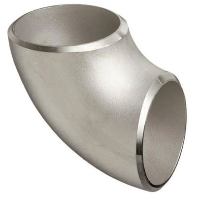
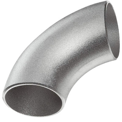
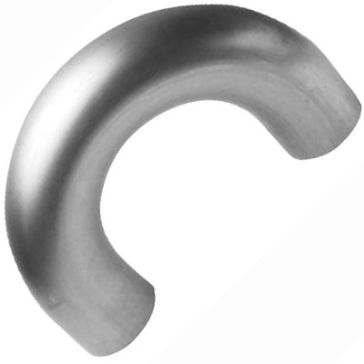
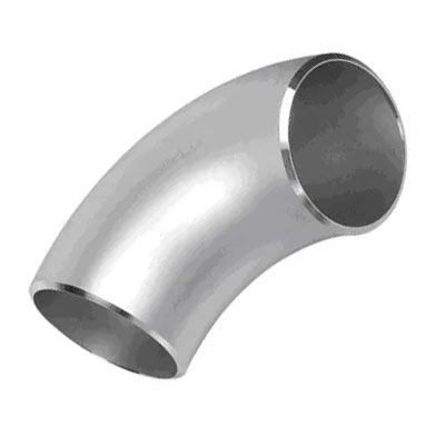
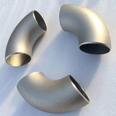
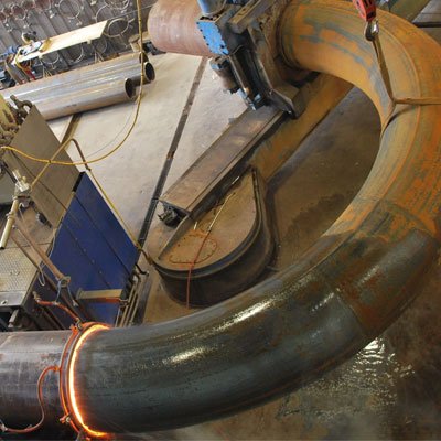
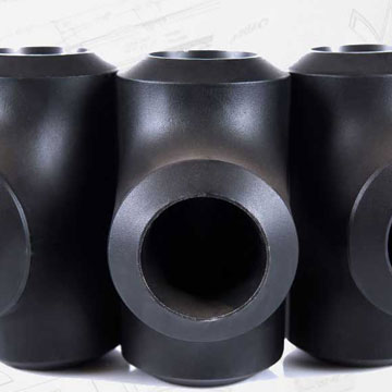
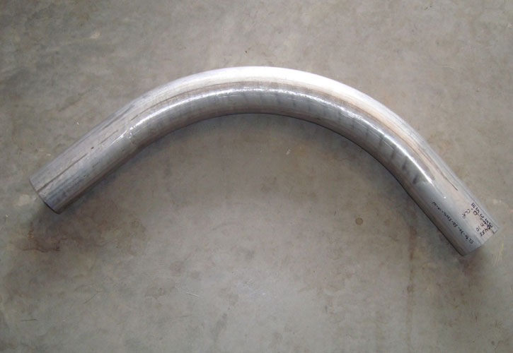
A piggable bend is a specialized type of pipeline bend designed to facilitate the passage of pipeline inspection gauges, commonly known as pigs, through the pipeline system. These bends are essential for maintaining and inspecting pipelines, ensuring their integrity and functionality. Piggable bends allow pigs—devices used for cleaning, inspecting, or maintaining pipelines—to navigate through bends in the pipeline. This ensures that the entire pipeline, including curved sections, can be inspected or cleaned effectively. By enabling uninterrupted pigging operations, piggable bends help maintain pipeline efficiency and reduce downtime.
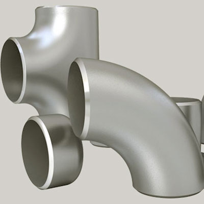
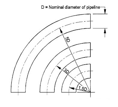
The design and construction of a piggable bend are crucial to ensuring its functionality and effectiveness in pipeline systems. These bends are engineered with a long radius to facilitate the smooth passage of pipeline inspection gauges, or pigs, minimizing the risk of obstructions or damage. The radius of a piggable bend is typically specified as 1.5D, 2D, or 3D, where "D" represents the diameter of the pipe, allowing for gradual curves that prevent excessive drag on the pigs. The diameter of piggable bends ranges from as small as 2 inches (50 mm) to as large as 72 inches (1800 mm) or more, depending on the pipeline's requirements.
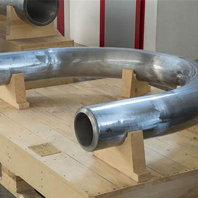
The installation and maintenance of piggable bends are vital to ensuring their optimal performance and longevity in pipeline systems. During installation, piggable bends must be precisely aligned and securely connected to the pipeline to facilitate the smooth passage of inspection gauges or pigs. Proper alignment minimizes the risk of obstructions and ensures that the bends do not disrupt the flow of the pipeline. Installation also involves verifying that all connections are leak-proof and that the bend is integrated seamlessly with the rest of the pipeline infrastructure.
Maintenance of piggable bends is equally important to maintain their effectiveness. Regular inspection and cleaning are necessary to identify and address any wear, corrosion, or blockages that could impact the functionality of the bend. Scheduled maintenance helps prevent issues that could compromise the integrity of the pipeline or impede pigging operations. Additionally, any signs of damage or deterioration should be promptly addressed, either through repairs or replacements, to ensure that the piggable bends continue to support efficient pipeline operations and inspection processes.


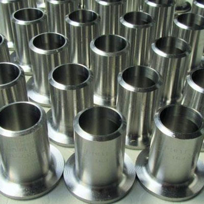
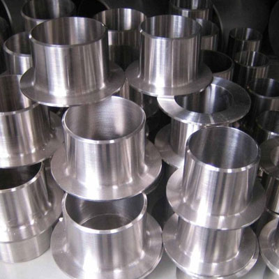
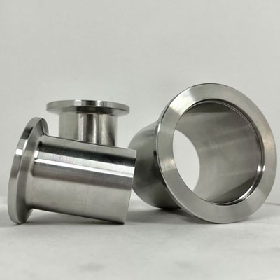
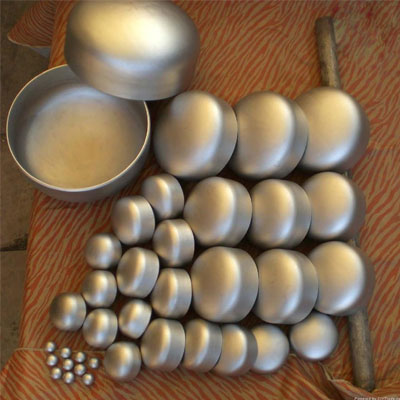
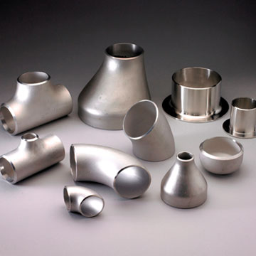
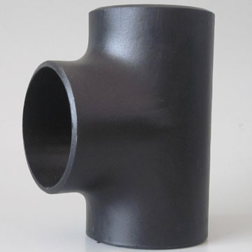
Industrial-Grade Buttweld Fittings: Tee | 45° Elbow | 90° Elbow | 180° Elbow | 1D Elbow | 1.5D Elbow | 3D Elbow | 5D Elbow | 10D Elbow | Hot Induction Bend | Piggable Bend | U Bend | Long Stub End | Short Stub End | Lap Joint Stub End | Caps
| Gauge | Stainless Steel Minimum Piggable Bend Radius Includes Minimum Closeness of Cutout to Bend |
Piggable Bend Radius (Refers to Inner Radius) |
|---|---|---|
| 11 gauge (0.120″ |3.05mm) | .5″ | .07″, .08″, .09″, .1″, .125″ |
| 14 gauge (0.075″ | 1.9 mm) | .275″ | .05″, .055″, .062″, .07″, .075″ |
| .375″ | .07″, .105″ | |
| .5″ | .09″, .11″, .115″, .12″ | |
| 1.375″ | .4″ | |
| 16 gauge (0.060″ | 1.52 mm) | .2″ | .035″, .05″ |
| .265″ | .05″, .055″, .075″, .08″ | |
| .375″ | .07″ | |
| .5″ | .105″, .12″ | |
| 18 gauge (0.048″ | 1.22 mm) | .2″ | .04″, .045″, .05″ |
| .265″ | .06″, .07″, .08″, .085″ | |
| .375″ | .1″, .125″ | |
| .5″ | .115″, .12″ | |
| 20 gauge (0.035″ | 0.89 mm) | .2″ | .05″ |
| .265″ | .06″, .07″ | |
| .375″ | .095″ | |
| 22 gauge (0.029″ | 0.74 mm) | .2″ | .05″ |
| .265″ | .04″, .08″ | |
| 24 gauge (0.024″ | 0.61 mm) | .2″ | .04″ |
| .265″ | .08″ |
| Pipe Diameter (inches) | Bend Radius (1.5D) | Bend Radius (2D) | Bend Radius (3D) | Bend Radius (5D) | Wall Thickness (inches) |
|---|---|---|---|---|---|
| 2 | 3.0 | 4.0 | 6.0 | 10.0 | 0.083 - 0.250 |
| 2.5 | 3.75 | 5.0 | 7.5 | 12.5 | 0.083 - 0.250 |
| 3 | 4.5 | 6.0 | 9.0 | 15.0 | 0.083 - 0.250 |
| 4 | 6.0 | 8.0 | 12.0 | 20.0 | 0.083 - 0.375 |
| 5 | 7.5 | 10.0 | 15.0 | 25.0 | 0.109 - 0.375 |
| 6 | 9.0 | 12.0 | 18.0 | 30.0 | 0.109 - 0.500 |
| 8 | 12.0 | 16.0 | 24.0 | 40.0 | 0.109 - 0.625 |
| 10 | 15.0 | 20.0 | 30.0 | 50.0 | 0.125 - 0.750 |
| 12 | 18.0 | 24.0 | 36.0 | 60.0 | 0.125 - 0.875 |
| 14 | 21.0 | 28.0 | 42.0 | 70.0 | 0.188 - 1.000 |
| 16 | 24.0 | 32.0 | 48.0 | 80.0 | 0.188 - 1.125 |
| 18 | 27.0 | 36.0 | 54.0 | 90.0 | 0.250 - 1.250 |
| 20 | 30.0 | 40.0 | 60.0 | 100.0 | 0.250 - 1.375 |
| 24 | 36.0 | 48.0 | 72.0 | 120.0 | 0.312 - 1.500 |
| 30 | 45.0 | 60.0 | 90.0 | 150.0 | 0.375 - 1.750 |
| 36 | 54.0 | 72.0 | 108.0 | 180.0 | 0.375 - 2.000 |
| 42 | 63.0 | 84.0 | 126.0 | 210.0 | 0.500 - 2.250 |
| 48 | 72.0 | 96.0 | 144.0 | 240.0 | 0.500 - 2.500 |
| 54 | 81.0 | 108.0 | 162.0 | 270.0 | 0.625 - 2.750 |
| 60 | 90.0 | 120.0 | 180.0 | 300.0 | 0.625 - 3.000 |
| 72 | 108.0 | 144.0 | 216.0 | 360.0 | 0.750 - 3.500 |
| Tolerance Type | Specification |
|---|---|
| Bend Radius | 1.5D to 3D (D = pipe diameter) |
| Dimensional Tolerances | |
| - Length | ±5 mm |
| - Diameter | ±1-2 mm |
| - Angle | ±1 degree |
| Ovality | ±2% of pipe diameter |
| Wall Thickness | ±10% of specified thickness |
| Surface Finish | Smooth; welds and seams ground flush; surface roughness per material standards |
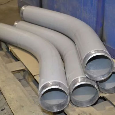
Piggable bend pipe fittings are specially designed bends that allow pipeline pigs (cleaning or inspection tools) to pass through smoothly without getting stuck.
Saudi Arabia, Singapore, Oman, United States, India, Kuwait, Australia, Peru, Philippines, United Kingdom, Argentina, Algeria, Bulgaria, Cameroon, Canada, Chile, Czech Republic, Djibouti, Dominican Republic, Ecuador, Germany, Ghana, Greece, Guatemala, Israel, Jordan, Mexico, Morocco, Myanmar, Panama, Poland, Qatar, Romania, Bolivia, Brazil, Netherlands, Malaysia, Mauritania, Slovenia, South Korea, Spain, Sri Lanka, Taiwan, Thailand, Tunisia, United Arab Emirates, Venezuela, Vietnam, Mauritius, Monaco, Russia.
Riyadh, Jeddah, Mecca, Medina, Dammam, Khobar, Abha, Tabuk, Najran, Buraydah, Singapore, Muscat, Salalah, Sohar, Nizwa, Sur, New York City, Los Angeles, Chicago, Houston, Phoenix, Philadelphia, San Antonio, San Diego, Dallas, San Jose, Kuwait City, Al Ahmadi, Hawalli, Salmiya, Jahra, Sydney, Melbourne, Brisbane, Perth, Adelaide, Canberra, Hobart, Darwin, Lima, Arequipa, Trujillo, Chiclayo, Piura, Manila, Quezon City, Cebu City, Davao City, Zamboanga City, Bacolod, Iloilo City, Cagayan de Oro, General Santos, Baguio, London, Birmingham, Manchester, Glasgow, Edinburgh, Liverpool, Leeds, Bristol, Sheffield, Newcastle, Buenos Aires, Córdoba, Rosario, Mendoza, La Plata, Algiers, Oran, Constantine, Annaba, Blida, Sofia, Plovdiv, Varna, Burgas, Ruse, Yaoundé, Douala, Garoua, Bamenda, Maroua, Toronto, Montreal, Vancouver, Calgary, Ottawa, Santiago, Valparaíso, Concepción, La Serena, Antofagasta, Prague, Brno, Ostrava, Plzeň, Liberec, Djibouti City, Santo Domingo, Santiago de los Caballeros, La Romana, San Pedro de Macorís, Puerto Plata, Quito, Guayaquil, Cuenca, Santo Domingo, Machala, Berlin, Hamburg, Munich, Cologne, Frankfurt, Accra, Kumasi, Tamale, Takoradi, Tema, Athens, Thessaloniki, Patras, Heraklion, Larissa, Guatemala City, Mixco, Villa Nueva, Quetzaltenango, Escuintla, Jerusalem, Tel Aviv, Haifa, Rishon LeZion, Petah Tikva, Amman, Zarqa, Irbid, Aqaba, Madaba, Mexico City, Guadalajara, Monterrey, Puebla, Tijuana, Rabat, Casablanca, Marrakesh, Fes, Tangier, Yangon, Mandalay, Naypyidaw, Bago, Taunggyi, Panama City, Colón, David, Santiago, Chitré, Warsaw, Kraków, Łódź, Wrocław, Poznań, Doha, Al Rayyan, Al Wakrah, Al Khor, Umm Salal, Bucharest, Cluj-Napoca, Timișoara, Iași, Constanța, La Paz, Santa Cruz, Cochabamba, Sucre, Oruro, São Paulo, Rio de Janeiro, Brasília, Salvador, Fortaleza, Amsterdam, Rotterdam, The Hague, Utrecht, Eindhoven, Kuala Lumpur, George Town, Johor Bahru, Ipoh, Shah Alam, Nouakchott, Nouadhibou, Rosso, Kaédi, Zouerate, Ljubljana, Maribor, Celje, Kranj, Velenje, Seoul, Busan, Incheon, Daegu, Daejeon, Madrid, Barcelona, Valencia, Seville, Zaragoza, Colombo, Kandy, Galle, Jaffna, Negombo, Taipei, Kaohsiung, Taichung, Tainan, Hsinchu, Bangkok, Chiang Mai, Pattaya, Phuket, Nakhon Ratchasima, Tunis, Sfax, Sousse, Kairouan, Bizerte, Abu Dhabi, Dubai, Sharjah, Al Ain, Ajman, Caracas, Maracaibo, Valencia, Barquisimeto, Maracay, Hanoi, Ho Chi Minh City, Da Nang, Hai Phong, Can Tho, Port Louis, Beau Bassin-Rose Hill, Vacoas-Phoenix, Curepipe, Quatre Bornes, Monaco, Moscow, Saint Petersburg, Novosibirsk, Yekaterinburg, Nizhny Novgorod, Mumbai, Delhi, Bangalore, Hyderabad, Ahmedabad, Chennai, Kolkata, Surat, Pune, Jaipur.